A 0.5-inch panel at 1600x1200 looks like a modest step up from a smaller display, but it changes the optical problem in ways that are easy to miss. The DM-OLED050-1005 is a 0.5-inch Micro OLED module running 1600x1200 at 120Hz with 1000 cd/m2 and a MIPI interface, built on a single-crystal silicon backplane with an integrated panel driver. That combination gives a head-mounted medical viewer a dense, fast image source. The cost appears in the optics: magnification, eye relief and stray light all have to be re-optimised around this specific geometry rather than inherited from an earlier design.
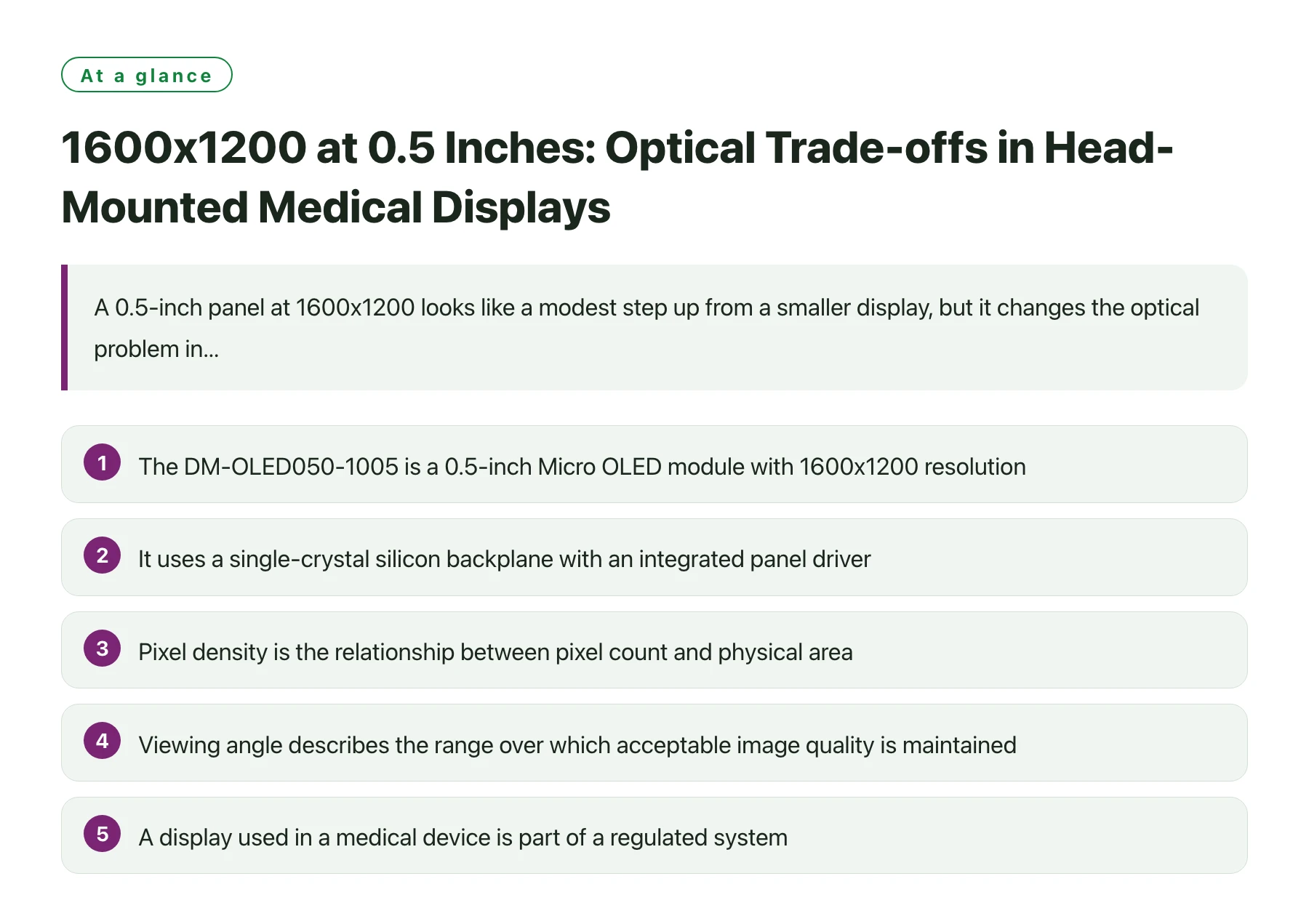
Key takeawaysThe DM-OLED050-1005 is a 0.5-inch Micro OLED module with 1600x1200 resolution, 120Hz refresh, 1000 cd/m2 brightness and a MIPI interface. · It uses a single-crystal silicon backplane with an integrated panel driver, which concentrates the drive electronics at the panel rather than in a separate assembly. · Pixel density is the relationship between pixel count and physical area, and it sets how much magnification the eyepiece can apply before the pixel grid becomes visible [1]. · Viewing angle describes the range over which acceptable image quality is maintained, and in a near-eye viewer it determines how much eye movement the design can tolerate [3]. · A display used in a medical device is part of a regulated system, so optical performance has to be reproducible unit to unit and documented [2].
Medical viewers are optics projects that happen to include a display. The clinical requirement, whether it is reading fine structure, following a procedure or reviewing an image with a colleague, translates into a field of view, a working distance and a resolution. The panel is chosen to satisfy those, and everything else follows.
The DM-OLED050-1005 provides 1600x1200 at 120Hz with 1000 cd/m2 over a MIPI interface in a 0.5-inch module, and it is built on a single-crystal silicon backplane with the panel driver integrated. The high refresh rate is unusual for a medical viewer and useful for anything involving live imaging or head-tracked content.
The optical trade-offs below are organised around three questions: how the pixel format constrains magnification, how the panel's size affects eye relief and the enclosure, and what a 120Hz source means for the rest of the optical and electronic design.
What the pixel format allows the eyepiece to do
Density sets the magnification ceiling
Pixel density describes how many pixels occupy a given physical area, and at near-eye distance it determines how far the optics can magnify before the pixel structure becomes visible [1]. A 1600x1200 panel in a 0.5-inch envelope provides enough density for a comfortable field of view without obvious grid structure, provided the eyepiece is designed for the specific image size rather than reused from a different panel.
The practical test is to view a fine-detail pattern and text at the extremes of the field. If the corners soften before the centre, the optical design is not delivering the resolution the panel can supply, and the limitation is in the eyepiece rather than the display.
Aspect ratio and the shape of the field
A 4:3 format at 1600x1200 is a different shape from the 16:9 panels used in consumer headsets, and it suits content such as medical images and instrument readouts that are themselves closer to square. Designing the eyepiece around this format avoids wasting pixels on a field the application does not use.
It also affects the mechanical envelope, because the panel's height is a larger fraction of its width than in a wide format. That changes where the module sits relative to the eyepiece and how much room remains for the harness and any baffling around the display.
Optical decisions that follow from this panel
| Decision | What the panel forces | Check that proves the choice |
|---|---|---|
| Magnification | Enough to fill the intended field without revealing the pixel grid [1]. | Fine-detail and text patterns viewed at the field edges, not only at the centre. |
| Eye relief | The distance from the last optic to the exit pupil that the wearer's face allows. | Measured with the widest and narrowest expected interpupillary spacing. |
| Exit pupil size | Large enough for head movement, small enough to keep the optics compact. | Luminance and sharpness sampled across the eye box in two axes. |
| Stray light control | Baffling and coating for a bright emissive source with a true dark state. | Dark-field inspection in a dark room with the module at working brightness. |
| Alignment tolerance | Positional accuracy between panel and eyepiece that the clinical task requires. | Assembly measurement repeated across a batch to establish the real tolerance. |
What 120Hz changes in a medical context
A 120Hz source is not only about smooth motion. In a head-mounted viewer it shortens the interval between a head movement and the corresponding image update, which reduces the mismatch between what the vestibular system expects and what the eye sees. For live imaging or for a clinician who moves their head while observing, that matters.
The cost is on the electronics and the power side. A higher refresh rate raises the data the link must carry and the power the panel and host consume, and it reduces the time available for any processing in the pipeline. The optical design has to accommodate the resulting thermal load, since a warmer panel changes its output slightly.
There is also a documentation angle. Device performance that depends on timing and optical alignment has to be verified reproducibly, because a display inside a medical device is part of a regulated system where performance claims need evidence [2]. Building the measurement into the assembly process is cheaper than reconstructing it during a review.
Viewing angle behaviour belongs in the same verification. Because the wearer's eye sits inside a defined region, the usable performance is the worst case across that region rather than the best case on axis [3]. A design that is measured only at the centre has not been verified at all.
Where the panel has already been selected, the optical work still benefits from an early look at the mechanical and interface details. Reviewing the 0.5" MIPI Micro OLED display module drawing alongside the first optical layout keeps the eyepiece, the baffling and the harness clearance in one design conversation, before any tooling is committed.
Verifying optical performance before the design freeze
Verifying a near-eye optical design is not a single measurement. It is a small set of measurements taken under defined conditions at the design eye position and repeated across units so that variation becomes visible. The list is short enough to run on every pilot unit, and complete enough to catch the defects that a magnified image exposes.
Start with alignment. Display a fine-detail pattern with strong local contrast, inspect the centre and the four corners of the field, and record whether the corners hold the detail the centre does. A centre-to-corner difference points to the optics or the mounting rather than to the panel, and it will not be fixed by changing the display.
Then measure uniformity. A flat mid-grey field makes brightness and colour variation easy to see, and recording it at the intended operating brightness rather than at maximum keeps results comparable between builds. Warm-up matters here: a measurement taken immediately after power-on describes a different panel state from one taken at thermal equilibrium.
Finally, check the dark state with the unit fully assembled. Stray light introduced by the enclosure only appears once the optical path is closed, and because the panel has a genuinely dark state the effect is easy to spot. Recording all three results against a unit serial number turns them into evidence, which is what a device programme needs when a reviewer asks how the design was verified.
Sources
Frequently asked questions
Is 1600x1200 enough resolution for a medical viewer?
That depends on the field of view and the clinical task. The useful check is to view the actual content through the intended optics and confirm that fine detail and text remain legible at the edges of the field, rather than judging by pixel count alone.
What does an integrated panel driver on a silicon backplane mean for the design?
The drive electronics are integrated with the panel rather than being a separate assembly, which simplifies the electrical interface to the module. The host still has to provide the correct power rails and the initialisation sequence over the display interface.
Does a 120Hz refresh rate matter for static medical images?
It matters when the image moves with the wearer's head, because the update interval affects how well the virtual image tracks head motion. For truly static views the benefit is smaller, and the power cost should be weighed against it.
How should a medical viewer verify optical performance?
With measurements taken through the assembled optics at the design eye position: alignment and sharpness across the field, uniformity, dark-state appearance and contrast. Recording those values per unit provides the evidence that a regulated programme needs.